And and Or nodes are Logic nodes that you can use in a policy model to specify whether or not policy execution should continue based on the results of the incoming logic paths.
Specifically:
The And node evaluates whether or not all incoming logic paths result in a value of true passed to the And node.
The Or node evaluates whether or not at least one incoming logic path results in a value of true passed to the Or node.
Note: Unlike other nodes which require all immediate predecessor nodes to be executed in order for the node to be, the Or node requires only one immediate predecessor node to be executed in order for the Or node to be executed.
In a policy model, Logic nodes must be preceded immediately by comparison or other Logic nodes. A value of true is passed to the Logic node when the logical result of the preceding node matches the logic path configured for the corresponding connection. For example, if the logical result of an immediately preceding condition node is no and the logic path configured for the corresponding connection is no, a value of true is passed to the Logic node.
The output of a Logic node is the logical result of the node. Specifically, when a Logic node is executed:
If the Logic node's criteria is met, the output (i.e., logical result) of the
node will be yes.
If the Logic node's criteria is not met, the output (i.e., logical result)
of the node will be no.
The logical results of Logic nodes are used by connections
to successor nodes in order to determine if the successor node
will be executed. You can use the Properties window for a connection
starting at a Logic node to configure a logic path for the connection. If you do not configure a logic path for a connection, a Yes path is assumed but does not appear on the model. The GE Digital APM system
will execute only the branches of a policy model where the logical result
of the Logic node matches the logic path defined for the corresponding
connection.
The following table summarizes what the result of each Logic node will
be for various input combinations.
Input A
Input B
And Node Result
Or Node Result
True
True
Yes
Yes
False
False
No
No
True
False
No
Yes
Note: For Or nodes, any input value that
is not true is considered false. This means that if a preceding
node is not executed or if errors occur during execution, the input from
the corresponding path will be false.
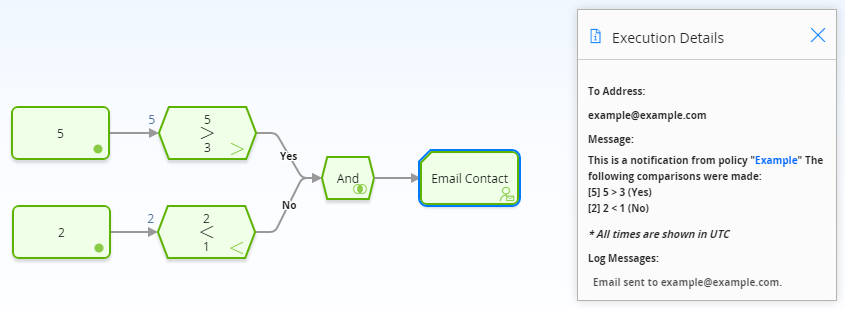
The following example illustrates how you can use the And node to monitor policy execution. To simplify this example, only constant values are used in the policy model. Consider the following nodes and connections, which are shown after validation has been run.
In this example, you can see that each node executed successfully. The logical result of the And node is yes because all incoming logic paths result in a value of true passed to the And node (i.e., the logical result of each preceding condition node matches the logic path of the corresponding connection). Therefore, policy execution continues past the And node.
The following example illustrates how you can use the Or node to monitor policy execution. To simplify this example, only constant values are used in the policy model. Consider the following nodes and connections, which are shown after validation has been run.
In this example, you can see that each node executed successfully. The logical result of the Or node is yes because the logical result of at least one incoming logic path results in a value of true passed to the Or node (i.e., the result of the 5 > 3Condition node is yes, which matches the logic path of the corresponding connection). Therefore, policy execution continues past the Or node.