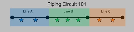
Suppose you have an asset, Piping Circuit 101, ) which contains three components, Line A, Line B, and Line C. On those components, there are multiple TMLs. The following image illustrates this example, where the components are represented by shaded regions, and the TMLs are represented by stars.
For a given asset, a TML Group can represent:
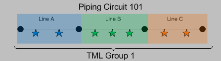
- All TMLs that exist on that asset. You would create a TML Group to represent all TMLs that exist on an entire asset if the asset is a standalone asset. You would create one TML Group to represent all of the stars.
-
A subset of TMLs that exist on one or more components that belong to the asset. Using this option, you could create:
-
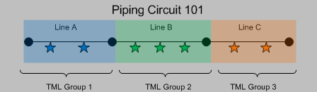
One TML Group per component, where the TML Group represents all TMLs that exist on that component. You would create three TML Groups, one to represent each set of stars.
-or-
-
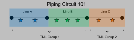
One TML Group for multiple components, where the TML Group represents all TMLs that exist on those components. Using the previous Piping Circuit 101 example, you could create two TML Groups, where one represents the blue and green stars and one represents the orange stars.
-
Additionally, throughout the life of the asset, you might identify one or more TMLs within a TML Group that you want to analyze separately from other TMLs. In this case, you can create additional TML Groups to represent any subdivision of an existing group of TMLs.
For example, suppose that an asset that you are analyzing in Thickness Monitoring represents a shell and tube heat exchanger. The shell and tube heat exchanger has two components, the shell side and the tube side, each with its own process flow. Since the corrosion environments of these components will differ, you might create the following TML Groups:
- TML Group - Shell Side
- TML Group - Tube Side
When you first begin analysis on the shell and tube heat exchanger, you are not sure what the TM corrosion data will show, (i.e., whether TML Group - Shell Side or TML Group - Tube Side will have more aggressive corrosion). After you have completed some analysis on the shell and tube heat exchanger, you notice that a subset of TMLs on the shell side near the nozzle have very high corrosion rates. At this point, you create a third TML Group, TML Group - Shell Nozzle to represent this component, and you move the TMLs associated with this component from TML Group - Shell Side to TML Group - Shell Nozzle.
Regardless of what they represent, all TML Groups in a Corrosion Analysis will be linked directly to a single asset. If you decide to use TML Groups, all TMLs in your Corrosion Analysis should be linked directly to TML Groups (rather than the asset to which the TML Groups are linked).